When we talk about an audio signal generated by an analogue (or virtual analogue) oscillator, we often describe it using three characteristics: its waveform, its frequency, and its amplitude. These, to a good approximation, determine its tone, its perceived pitch, and its volume, respectively. But there is a fourth characteristic that is less commonly discussed, and this is called the ‘phase’ of the signal.
Consider the humble 100Hz sine wave. You might think that this can be described completely by its frequency and its amplitude and, in practice, this is true provided that you hear it in isolation. But now consider two of these waves, each having the same frequency and amplitude. You can generate these by taking a single sine wave and splitting its output, passing one path through a delay unit as shown in figure 1. If no delay is applied, the two waves are said to be ‘in phase’ with one another (or, to express it another way, they have a phase difference of 0º) and, as you would imagine, you could mix them together to produce the same sound, but louder.

Now let’s consider what happens when the waves are ‘out of phase’, with one climbing away from ‘zero’ at the same time as the other drops away, as shown in figure 2. In this case, the second waveform is offset by half a cycle (a phase difference of 180º) with respect to the first and, if you mix them, they cancel each other out. In isolation, both waves sound identical, but mixing them results in silence. Given that this signal has a frequency of 100Hz, its period is 10ms. Consequently, the offset between the two waves in figure 2 (half a period) is exactly 5ms. This is a remarkable result because it tells you that, for a single frequency, a precise delay and a mixer can act as a perfect filter!

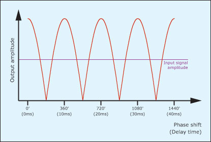
The results illustrated in figures 1 and 2 demonstrate perfect addition and perfect cancellation of a 100Hz sine wave but, if you combine the waves with phase differences other than 0º or 180º, you obtain different degrees of addition or cancellation. As you sweep the relative phase of the two signals from 0º to 360º the output from the system varies as shown in figure 3.

So far, so good… A phase difference of 180º results in cancellation while a phase difference of 0º or 360º results in maximum reinforcement. But there’s nothing stopping us from applying delays that result in phase differences greater than 360º, and a phase difference of 361º has the same effect as one of 1º, 362º has the same effect as 2º… and so on ad infinitum. So, if you take a sine wave, split it into two paths, apply a delay to one path and mix the signals again, the sound will come and go as you adjust the delay time. In the case of the 100Hz sine wave, cancellation occurs with delays of 5ms, 15ms, 25ms…, and maximum reinforcement occurs with delays of 10ms, 20ms, 30ms… and so on. (Figure 4.)

Now let’s turn this concept on its head. If there are many delay times that will result in cancellation of a 100Hz signal, it seems reasonable to surmise that there are many frequencies that will be cancelled by a given delay time. This turns out to be true, and the lowest frequency cancelled by a given delay “D” expressed in seconds is 1/2D. The next cancellation occurs at 3/2D, the next at 5/2D, the next at 7/2D and so on. Returning to our example, therefore, a delay of 5ms generates a fundamental cancellation at 100Hz, but it also cancels signals lying at 300Hz, 500Hz, 700Hz… and so on, all the way up through the spectrum, with frequencies lying between these figures attenuated as shown in figure 5. The resulting filter response looks much like a broad toothed comb.

Of course, sine waves are rather special cases, but complex signals such as music and speech can be represented by an infinite number of sine waves that describe all the frequencies present. So, for a given delay, every signal component will be reinforced or attenuated according to its frequency and the delay applied, and the resulting holes in the output spectrum are what give the comb filter its instantly recognisable character.
Finally, let’s consider what happens when the delay time is not constant but fluctuates in some fashion. In this case, the holes in the spectrum will sweep across the spectrum in some fashion, creating effects that include flanging, phasing and chorusing. Furthermore, these and other effects can be further reinforced by positive feedback (called ‘regeneration’ or ‘resonance’) to create some of the most interesting sounds and effects obtainable from subtractive synthesis.
Using the comb filter in Thor
I’ve discussed the theory behind comb filters in a bit more depth than usual because, when you knowhow they do what they do, you can design some amazing sounds using them. But you probably won’t stumble upon these by accident.
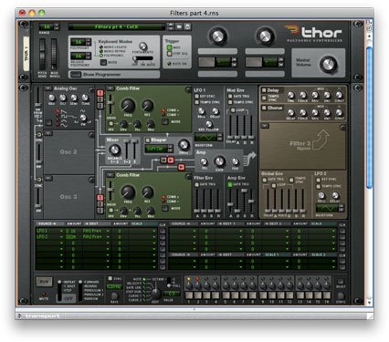
Let’s start by proving the concepts outlined above. Figure 6 shows a basic Thor patch, with a sine wave generated by Osc 1 being swept upward by applying the Filter Envelope to the oscillator frequency in the modulation matrix. There’s no filtering applied, just a gentle Attack and Release in the Amp Env to smooth the start and finish of the sound. If you play a note, you obtain the smooth upward sweep you would expect:
(Click to enlarge)
Now add a comb filter as shown in figure 7, with the filter frequency set to its minimum of 39.4Hz (approximately 25.4ms). Playing the same note as before demonstrates that the amplitude of the signal now changes from silent to loud to silent to loud as the pitch increases, with silences at 59.0Hz, 98.4Hz, 137.8Hz… and so on up the spectrum:
Not convinced? OK, then look at figure 8, which shows part of the audio in sound #2. Silent – loud – silent – loud – silent – loud… exactly as predicted.
(Click to enlarge)
(Click to enlarge)
A more interesting result is obtained if you replace the sine wave with something harmonically complex such as a sawtooth wave. A 100Hz sawtooth comprises components at 100Hz, 200Hz, 300Hz, 400Hz… all the way up to the upper limit of the spectrum that your audio system can handle. Consequently, if you sweep the pitch, you won’t hear the amplitude of the signal change very much, but you’ll hear its harmonic content change as various harmonics are reinforced or silenced. You can hear an unfiltered sawtooth sweep in sound #3:
And the same sweep passing through a comb filter in sound #4 .
Next, rather than sweep the pitch of the oscillator to alter the harmonic content of the waveform, let’s leave the pitch of the oscillator constant and alter the frequency of the comb filter. To demonstrate what this can do, let’s start by playing a simple chord with no comb filtering applied:
We can make this more interesting by reintroducing the filter and modulating its frequency using LFO1 as shown in figure 9. If we set the LFO rate to an appropriate value (which turns out to around 6Hz), we obtain sound #6:
Amazing… this is like turning on the Ensemble button of a cheap string synth! However, because there’s just a single modulation, you can hear a distinct “wa-wa-wa-wa-wa” in the timbre, so we can remove this and add greater depth to the patch by applying a second modulator to Filter 1 or by adding a second audio path, placing a second comb filter in the Filter 2 slot and modulating this at a different rate. I have chosen the latter approach with LFO2 as the modulator, using a rate of around 1Hz and a somewhat greater modulation depth than I used in the first path. You can see the patch in figure 10, and hear the result in sound #7. This is much nicer:
(Click to enlarge)
(Click to enlarge)
This ‘dual-filtered’ sound is perfectly useable, but it retains perhaps too much of the brightness of the initial sawtooth wave, so you should EQ this to taste. I have done so by placing a low-pass filter in the Filter 3 slot (figure 11). With a cut-off frequency of around 2.5kHz, I obtained sound #8:
(Click to enlarge)
If this still isn’t fat enough for you, you can add more oscillators to the patch. Figure 12 shows it with three detuned sawtooth oscillators instead of the single oscillator used above. Even without filtering, this would be an imposing patch, but when played through the dual filters, it’s a monster:
With the low-pass filter in the Filter 3 slot, it’s heavier and darker:
To illustrate this further, I’ve played a well-known chord sequence and recorded it as sound #11 (without EQ):
and as sound #12 (with EQ). Use with care!
(Click to enlarge)
Creating something a bit more radical
There’s a good reason why comb filters are so good at creating ensemble sounds: ensemble circuits typically comprise two, three or four variable delay lines followed by a mixer. Or, to put it another way, they comprise two, three or four modulated comb filters. But there’s something that a synthesiser’s comb filter has that a typical ensemble effect does not, and that’s a feedback loop. In a low-pass filter, the gain of this loop determines the amount by which the filter amplifies any signal components lying at or near its cut-off frequency. In a comb filter, increasing the value of the RES will emphasise ALL of the ‘humps’ in the filter’s response. So let’s return to the sawtooth sweep that created sound #4, but with the RES knob turned to its maximum rather than its minimum. As you can hear, the result is radically different:
Another interesting result is obtained if you leave the pitch of the oscillator unaffected and sweep the cut-off frequency of the comb filter. In sound #14 you can hear the harmonics of the sawtooth wave being picked out as the peaks of the comb travel upward in frequency until, at the end, they are so high up the spectrum that the sawtooth wave is heard almost unaffected:
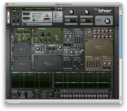
This is all well and good, but it’s when you realise that a highly resonant comb filter can generate a harmonic series that things get really interesting. Figure 13 shows a patch that uses a resonant comb filter to carve the spectrum from a noise generator into something resembling an harmonic oscillator, with the overall shape of the resulting spectrum determined by the colour of the initial noise. If you modulate the noise colour using an LFO as shown, you can create some wonderful, evolving textures. The three bass notes in sound #15 demonstrate this, sounding much like an E-bow applied to a trans-Atlantic cable:
Taking this to the extreme, I added some external effects (chorus, EQ and reverb) to produce sound #16 . This might win me the job as sound designer for the next instalment of the Aliens saga, but it’s still just noise passed through a single comb filter!
(Click to enlarge)
You can experiment with the patch in figure 13 to create a huge range of sounds ranging from menacing basses through to delicate, aetherial pads and voices. But, before finishing, there’s another use for the comb filter that I would like to demonstrate. If you pass a cyclic waveform through a highly resonant comb filter, you enter a new realm of sound design that involves convolving one harmonic series using a second. Think of it like this… you’re feeding a complete harmonic series into the filter, but you’ll only hear an output if one or more of the harmonics lie at the same frequencies as one or more of the filter’s pass-bands. Once you’ve got your head around this, you can devise all sorts of ways to generate interesting sounds. Figure 14 shows a patch in which a sawtooth wave that’s tracking the keyboard conventionally at 100% is being modified by a comb filter that’s tracking the keyboard at 90%. This means that different harmonics are being picked out depending upon the pitch, so each note that you play has a slightly different timbre from the others. You can set this up in many ways, but I rather like the bell-like timbre in sound #17 which, although it sounds a bit like AM or FM synthesis, would be all but impossible to obtain using other methods:
(Click to enlarge)
There are much more radical things that you can do with this patch, and sweeping the filter frequency manually will reveal some of these. You could also add a second comb filter and come up with all manner of interesting ways of making the resulting signals interact with each other and the source signal(s) you choose to put through them. To be honest, I could go on for days showing you how to get sounds out of comb filters. They are among the most powerful and radical sound-shaping tools at your disposal. Please use them.
Text by Gordon Reid


